I Reverse Engineered Jane Street's ASIC Puzzle
Jane Street's ASIC puzzle hands you exactly one file: puzzle.gds. No netlist, RTL or schematic, just the raw physical layout of a chip. It is the same file a fab would use to actually manufacture it. I had to reverse-engineer everything else myself: what gates it contains, how they're wired, what makes it tick and what makes it print an answer.
TL;DR: I extracted a full working simulation of this chip from that layout file, debugged my way through a stretch where every single signal read as unknown, used a SAT solver to figure out what input the chip actually wants, and then found something I wasn't expecting at all. I found a solved Star Battle puzzle. The chip is a hardware constraint checker for a logic puzzle, wired directly into silicon.
The puzzle: find the circuit's purpose from its layout file and nothing else
This is the entire file I was given:

A GDS file is polygons on layers. It's normally the last thing to exist in a chip design flow, the output you hand to a fab. This puzzle inverts the entire normal direction of hardware design: instead of going source → netlist → layout, I had to go the other way around.
The chip only exposes six ports: I (a 1-bit serial input), O[7:0], clk, enable, rst_n and success. Feed it a bitstream and success either goes high or it doesn't, with O printing something either way. That's pretty much everything I had at this point. More about it on their blog.
Why I took this on
I'm a pre-final year ECE undergrad. I've written RTL before and run a few designs through OpenLane, so netlists, synthesis and simulation were familiar ground. But tearing a GDS file apart was new territory. I've always liked reverse engineering, and this was the closest thing to my actual interest in chips that I'd found. Of course I couldn't pass it up.
My setup: WSL Ubuntu, KLayout's Python API, Magic, Yosys, Icarus Verilog, the sky130A PDK and Python scripts.
The approach at a glance
Before getting into the details, here's roughly the shape of what it took to get from that layout file to an answer:
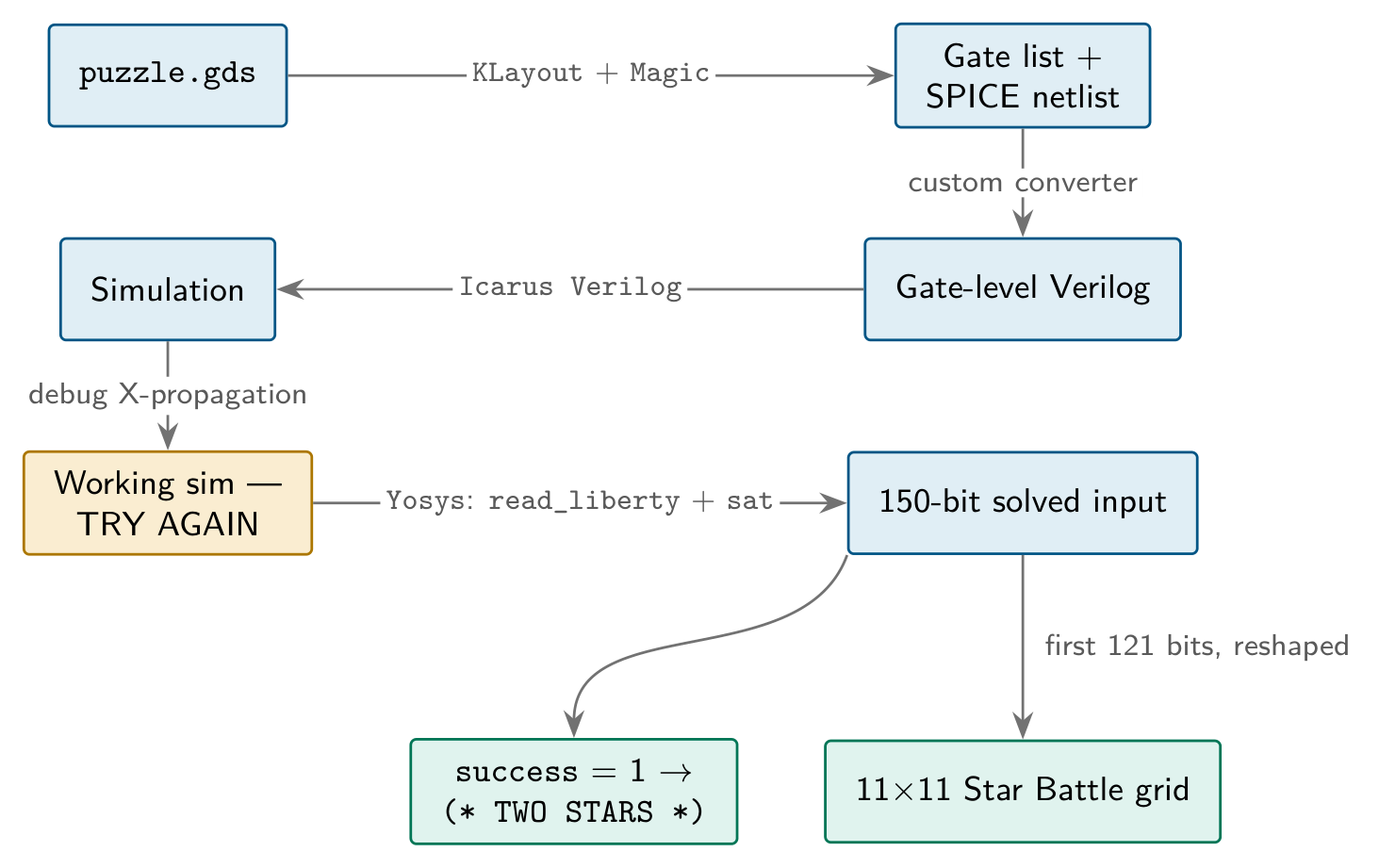
Every step on that chart broke at least once before it worked. Here's how each one actually went.
Building a working model of the chip
The puzzle includes a warmup/ folder, a tiny adder pushed through the entire flow with every intermediate file included: source Verilog, netlist, DEF, final GDS. A complete answer key for a smaller problem. Before pointing anything at the real puzzle, I tested and validated every tool against the known warmup files first. This paid off later, because whenever something broke I already knew it wasn't the extraction, since that stage had already proven itself independently.
First job was figuring out what was actually in the chip. I wrote a script using KLayout's Python API to list every cell instance with its placement:
722 logic gates
 92 flip-flops
  6 constant cells
    filler cells (caps, diodes), no logic
Two boxed cells matched what the README calls the “output generator”. I set it aside for later.
Getting the actual wiring out took more fighting. Magic wouldn't even parse the GDS at first. It hadn't loaded the sky130 tech file (already installed on my machine) so it had no idea what the layout layers meant. I found the files and pointed Magic at them, but hit a version wall immediately after: my Magic was too old for the tech file. After building Magic from source, extract all → ext2spice finally gave me a full SPICE netlist.
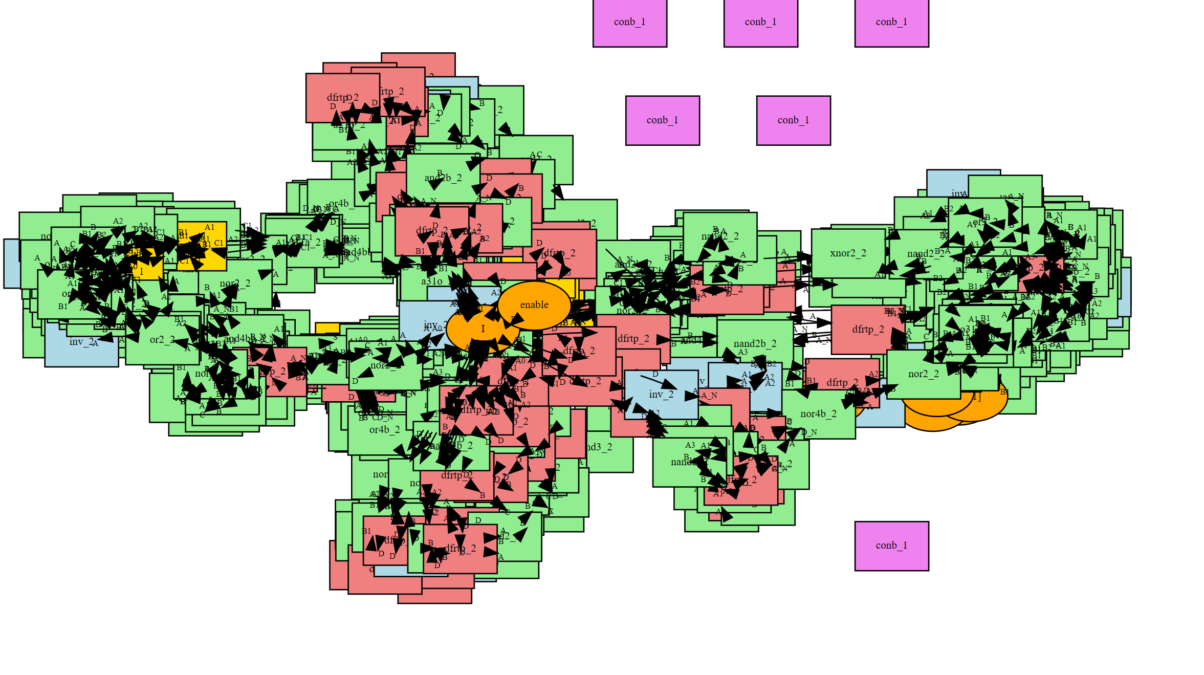
I also tried netgen to cross-check the extraction but its output came out at the transistor level, the wrong shape for what I needed, so I abandoned that path and wrote my own SPICE-to-Verilog converter instead. That is what ended up working. From the netlist I built a connectivity graph and a script to walk backward from any given net. Every net in the design turned out to have exactly one driving signal. Trying to render the entire graph in graphviz just to look at it, on the other hand, did not work at all. If you want to look at it, here you go:
Turning that netlist into something runnable took a few small fixes: collapsing Magic's separate O[0], O[1]… ports into a proper output [7:0] O bus, and stripping power-related pins like VPB/VNB that the sky130 Verilog models don't actually expose. After that: a clean compile, and a chip I could actually simulate.
Everything read X
This was the longest stretch of the whole puzzle. I wrote a testbench to run against the sample input:
t=5000  O=xx (x)  success=x
FINAL:  O=xx (x)  success=x
Everything compiled and ran but success stayed permanently unresolved. Getting to the actual cause meant ruling out a sequence of wrong theories first:
- an undriven net (wrong, a grep had just missed the driver);
- escaped whitespace splitting nets in two (wrong, connectivity was actually fully intact);
- a disconnected clock tree (wrong, the clock was toggling fine).
After checking the clock, naturally the next thing I checked was the reset. And bingo, that turned out to be the culprit.
The relevant flop has an asynchronous, active-low reset held low since time zero. It should have settled to 0 immediately but it hadn't. The flops weren't resolving at all. The sky130 flop models are built on UDPs (user-defined primitives) with a NOTIFIER pin used for timing checks. My netlist never connected it, so it read x. And an unconnected NOTIFIER forces the output to x forever. Every flop in the design was broken this way.
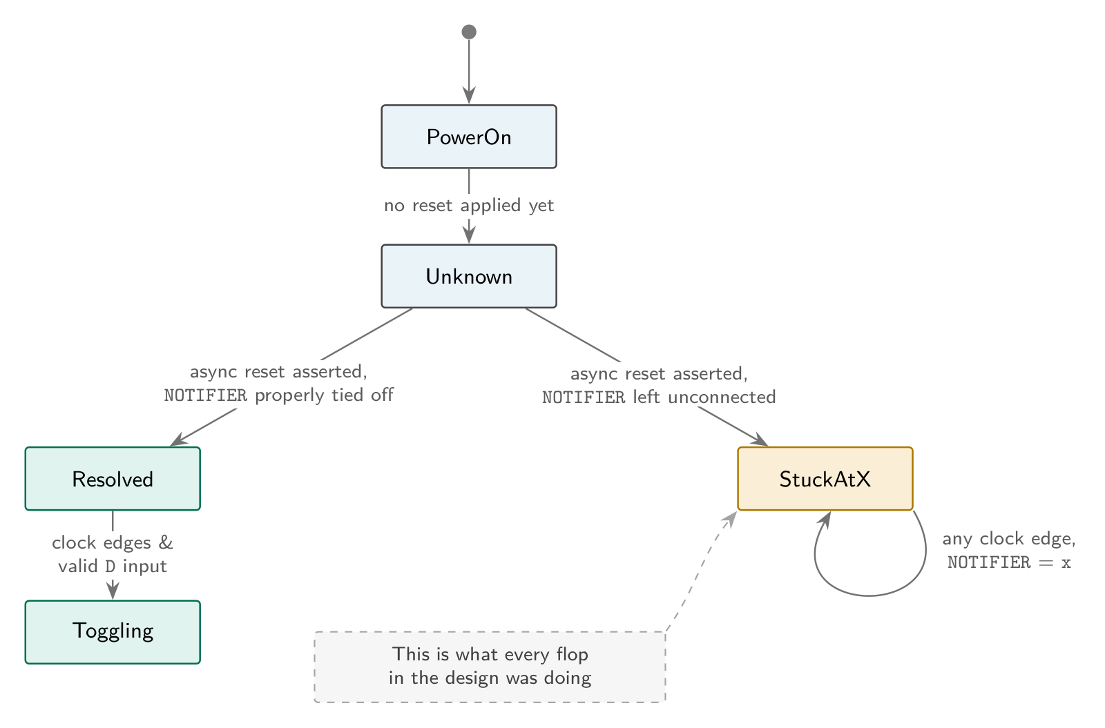
Fix: compile with `define FUNCTIONAL, swapping the UDP-based models for behavioral ones. Result:
t=1265000  O=54 ( 84)  success=0
...
54 52 59 20 41 47 41 49 4e decodes to TRY AGAIN. Not the answer, but a chip I had rebuilt entirely from a layout file was now producing legible English. This single result confirmed the extraction, the Verilog conversion and the simulation were all correct at once. It also confirmed the sample input in the puzzle is a deliberate decoy. From now on any input I could think of was cheap to test.
It wasn't a fixed comparator
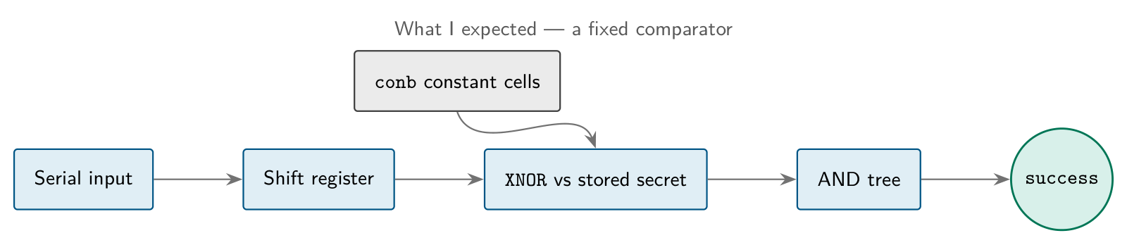
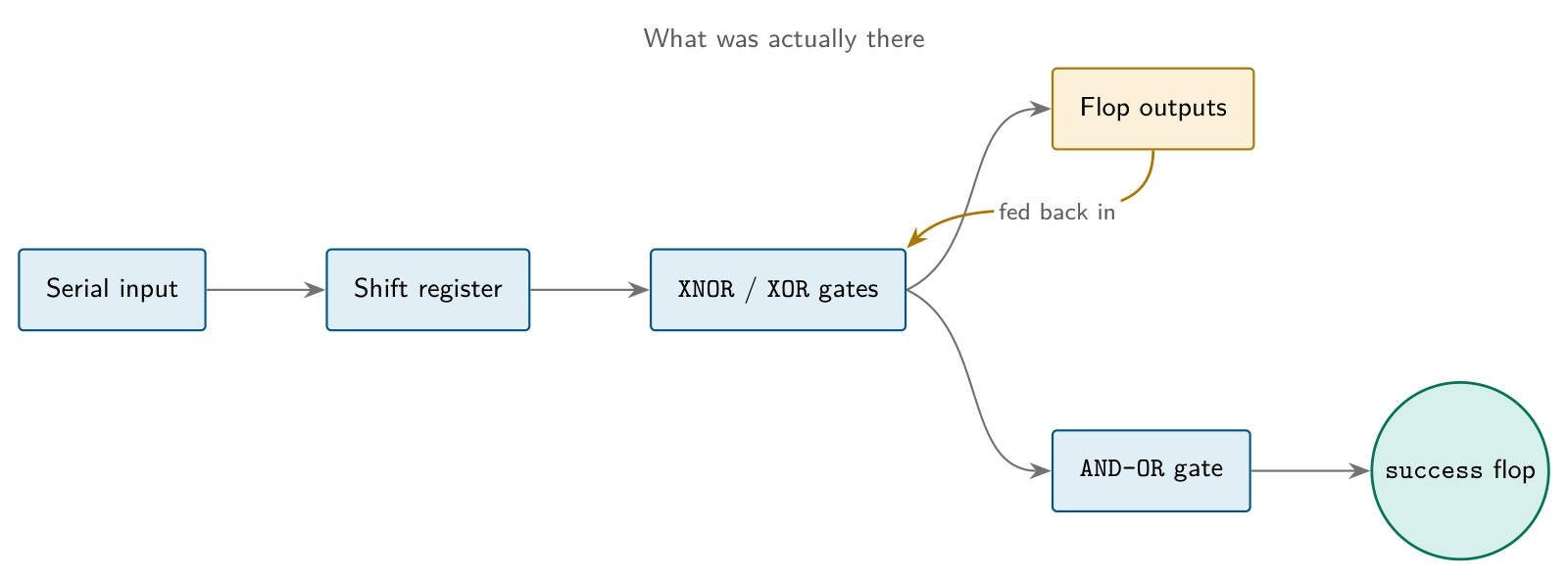
My first assumption was a comparator: shift the input into a register, XNOR it bit-by-bit against a stored secret, AND the results together. If that's right, the secret should be sitting somewhere in the netlist. I traced the fan-in cone of success and found a flop fed by an AND-OR gate and then by a small AND cluster. Widening the search turned up 12 XNOR gates. Everything as expected for equality checking.
But here's the twist: tracing what actually feeds those XNORs, none of them compare against a fixed constant. Their inputs are other XOR/XNOR gates and flop outputs, chained across cycles. This meant the input has to be solved for.
Here's a clearer view of what I assumed vs what was actually there:
That meant a SAT solver. Hand the whole netlist to Yosys, assert success = 1, unroll enough cycles, let it work backward for an input. Getting there also had some issues. The Yosys I had was too old to load cells with real logic attached; upgrading it fixed that. The async-reset flops also needed rewriting into synchronous equivalents before the design would even import cleanly.
The first actual solve came back UNSAT, because my own constraint was wrong: it forced success high at every single timestep instead of just the last one. I fixed it and it returned SAT with a full 150-cycle input, which then failed in my own simulator anyway because I'd left enable and rst_n completely free. Pinning both to their real values finally produced a sequence that worked:
t=1265000  O=28 ( 40)  success=1
t=1275000  O=2a ( 42)  success=1
t=1285000  O=20 ( 32)  success=1
t=1295000  O=54 ( 84)  success=1
...
28 2a 20 54 57 4f 20 53 54 41 52 53 20 2a 29 decodes to (* TWO STARS *). Fifteen clean ASCII bytes, success held high the entire readout.
The twist: a Star Battle puzzle inside the chip
That XOR/XNOR chain feeding success had never actually looked like a normal comparator. I didn't know what it really was until I looked closer at the input bits themselves.
I went high exactly twice in the first 10 cycles, twice in the next 10, and kept that pattern going for roughly 120 cycles. The pattern broke after 121. 121 is a perfect square, so I tried arranging it as an 11x11 grid. Every row had exactly 2 marked cells. Every column had exactly 2 marked cells. And no two marked cells touched.

That's the rule set of Star Battle, the logic puzzle where you place a fixed number of stars per row, column and region so that none of them touch.
Which made sense of everything I'd found tracing success earlier. It was never a comparator, it's a constraint checker for Star Battle's actual rules. Feed it a valid Star Battle solution and success goes high and the output generator prints the reward string; otherwise it prints “TRY AGAIN”.
Easter eggs
A few things placed on purpose that I noticed while solving the puzzle:
example_inputs.vcdis timestampedSat Dec 31 23:59:60 2016.- The
$versionstring inside that same VCD file: “Leave no stone unturned! But for this file, consider looking at it in a waveform viewer instead.” - The first 121 bits of the input decode into a valid 11x11 Star Battle grid.
- Feeding the chip a wrong input prints TRY AGAIN on
O[7:0].
Tools
KLayout, Magic, Icarus Verilog, Yosys, netgen (tried and abandoned), graphviz (tried and abandoned) and some custom Python scripts for the GDS → graph → Verilog pipeline.
Final lines
Going into this, having never really taken apart a GDS file, the closest I'd gotten to physical layout was watching it happen inside a tool. Taking on something like reverse engineering an actual fabricated chip's mask was honestly one of the most fun technical rabbit holes I've been down. 20 days, more dead ends than I expected, and I came out having learned more about chips, GDS extraction, gate-level simulation and SAT solving than I would have from a semester of coursework.
Huge thanks to Jane Street (X / LinkedIn) for putting a challenge like this together. Really excited for their next puzzle announcement later this year.