A neural network on a chip I built
This is a Basys 3 FPGA playing LunarLander. Every action comes from hardware I wrote in SystemVerilog: a small CPU of my own driving a 4x4 grid of multiply-accumulate (MAC) units. You could run the same network in PyTorch in a few lines, so it is worth being clear about what is different here. Nothing on the board runs PyTorch, or any software at all except my own 50-instruction program. The network is computed by the circuits themselves. The laptop runs the game, sends the board 8 numbers per frame and draws whatever action comes back.
The short version:
- A 4x4 weight-stationary systolic array of INT8 MACs, driven by a single-cycle CPU that runs my own 10-instruction ISA.
- One decision takes 24,290 clock cycles, 0.24 ms at 100 MHz. Getting the bytes over UART takes 0.78 ms, more than 3 times longer than the math.
- The whole network shares one rescale constant, so the hardware needs only one requant block. The cost is that layer 2's weights only use -11 to 11 out of the INT8 range.
- In simulation the hardware matches a NumPy integer model bit for bit at every layer, on all 20 test inputs.
- It uses 3.5% of the chip's LUTs and 24 of its 90 DSP slices.
The post goes hardware first, then the numbers that run on it, then the board.
The compute: a systolic array
Every layer of the policy is a matrix-vector multiply followed by ReLU. One decision through 8 → 128 → 128 → 4 is about 18,000 MACs, and the 128 × 128 layer alone is 16,384.
The multipliers are the easy part. Feeding them is the hard part, because every MAC needs a weight and an activation from memory. A systolic array gets around that by making every value it fetches do several MACs.
A 4x4 array doing a matrix multiply
The grid is 16 processing elements (PEs), and each one holds a single weight. Activations move one PE right per cycle and partial sums move one PE down. Each PE multiplies the activation passing through by its weight and adds that to the sum coming from above. Each column's sum leaves the bottom as one output.
The inputs go in staggered, row 0 first and row 3 three cycles later, so each activation meets its partial sum on the right cycle. A deskew lines the outputs back up. One vector comes out at cycle 7. Four back to back finish at cycle 10, not 28, because the array works on several vectors at once.
Each activation gets used by 4 PEs as it moves along its row, and with several vectors streaming, each weight is reused for every one of them. That reuse is the whole point of the layout.
Weights stay put
Something has to stay fixed while the rest moves. I pin the weights, which is called weight-stationary, the same choice as Google's first TPU. One 128-bit read loads a whole 4x4 tile of INT8 weights in a single cycle. The catch is that my design sends one vector per tile, so I get the activation reuse but not the weight reuse. Batching inputs through each tile is the obvious upgrade.
One PE is one DSP slice
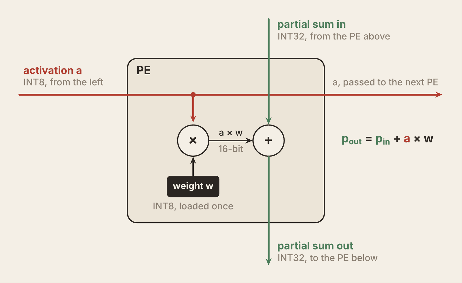
A PE is an 8-bit multiply and a 32-bit add, which maps exactly onto one DSP48E1 slice. The accumulator is wide because sums grow: 129 products of 16 bits each need about 23 bits, so 32 is the safe size. The whole array uses 16 of the chip's 90 DSPs.
The array is passive. It does nothing until something loads a tile, feeds it activations and tells it to go.
Driving the array: an ISA and a small CPU
The array only ever needs the same few commands, repeated thousands of times: load weights, load activations, multiply, wait. After the last tile of a group, apply ReLU and store. So I built a CPU that does exactly that and nothing else.
10 instructions instead of RISC-V
A RISC-V core would work, but it is built to run any program and I only ever run one. So I wrote a 10-instruction ISA with just what the array needs. Google's first TPU has the same shape at a much larger scale. Its core instructions are read host memory, read weights, matrix multiply, activate and write host memory, and mine ended up as nearly the same list.
Every instruction is 32 bits: a 6-bit opcode, two 5-bit register fields and a 16-bit immediate. Eight registers hold addresses and loop counters. Four instructions are housekeeping (LI, ADDI, LOOP, HALT), four talk to the array (M_LD_W, M_LD_A, M_MUL, STATUS) and two finish a group of outputs (ACT, M_ST).
Two holes I found on paper
Before writing any RTL I walked a real layer through the ISA by hand, and it broke twice. There was no way to get results out of the accumulators, so I added M_ST. And LOOP could only read one register, so it could not branch. Now it decrements a register and jumps back if the result is not zero.
A single-cycle CPU that stalls
Fetch, decode and execute are chained inside one clock cycle, not pipelined, so each instruction finishes before the next one starts. Matrix instructions go to the MXU controller, a state machine that sequences the array.
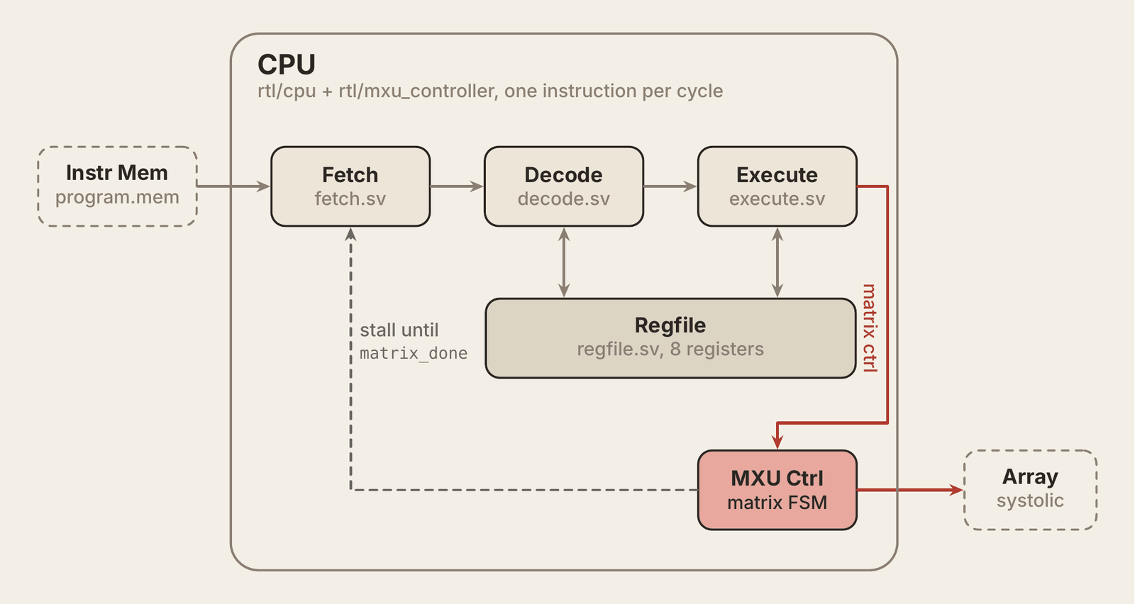
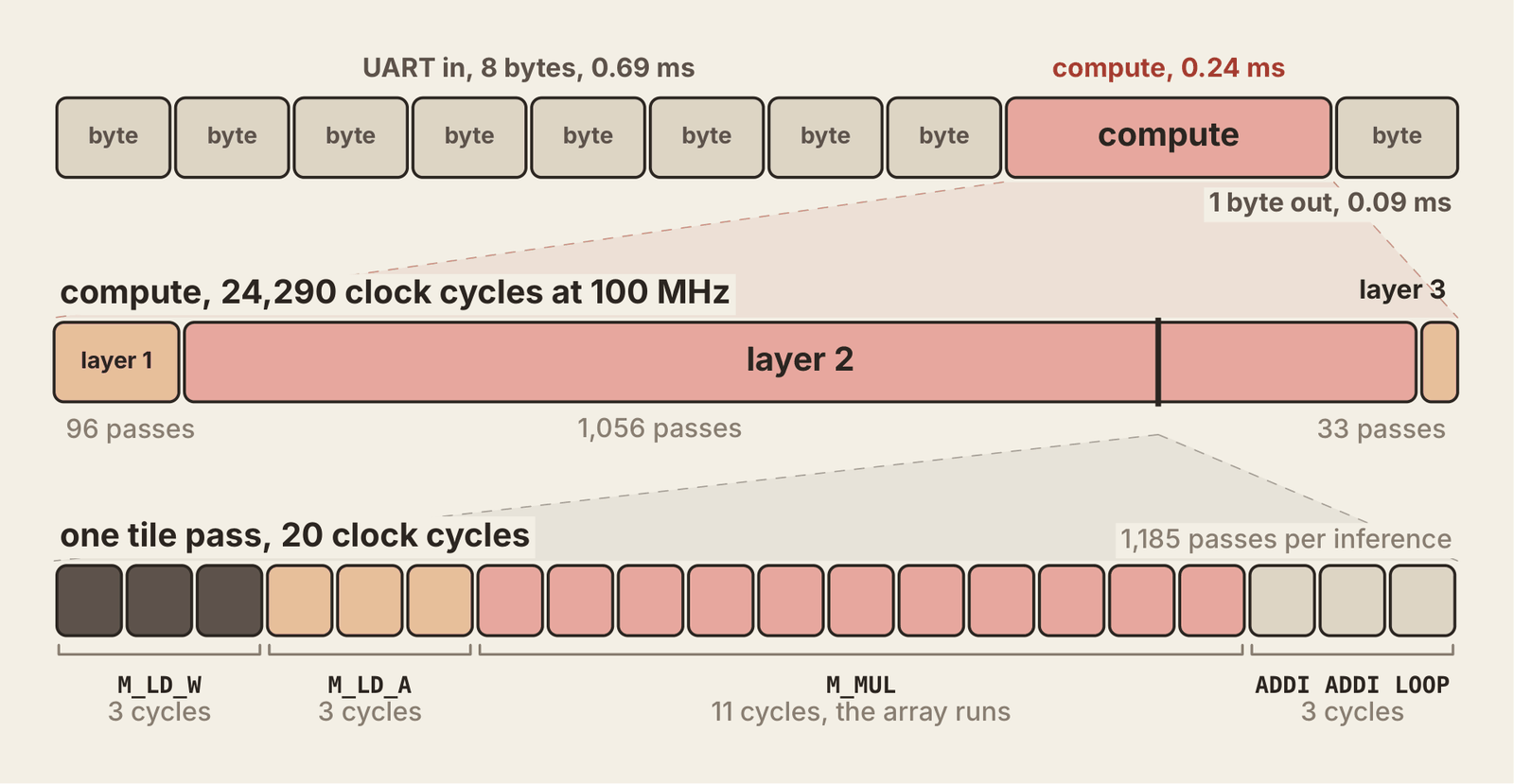
A matrix pass takes about 20 cycles while the CPU issues one instruction per cycle. So one line freezes the program counter until the array is done:
stall = (is_m_op && !matrix_done) || is_halt;
HALT reuses the same line to stop for good.
The program writes itself
Layer 2, the 128 × 128 one, is 32 groups of 4 outputs. Each group loops 33 times, 32 tiles for the 128 inputs and 1 for the bias, which gets folded into the weights. A script generates all of this from the layer shapes, and the whole network comes out to 50 instructions.
The whole machine: one inference end to end
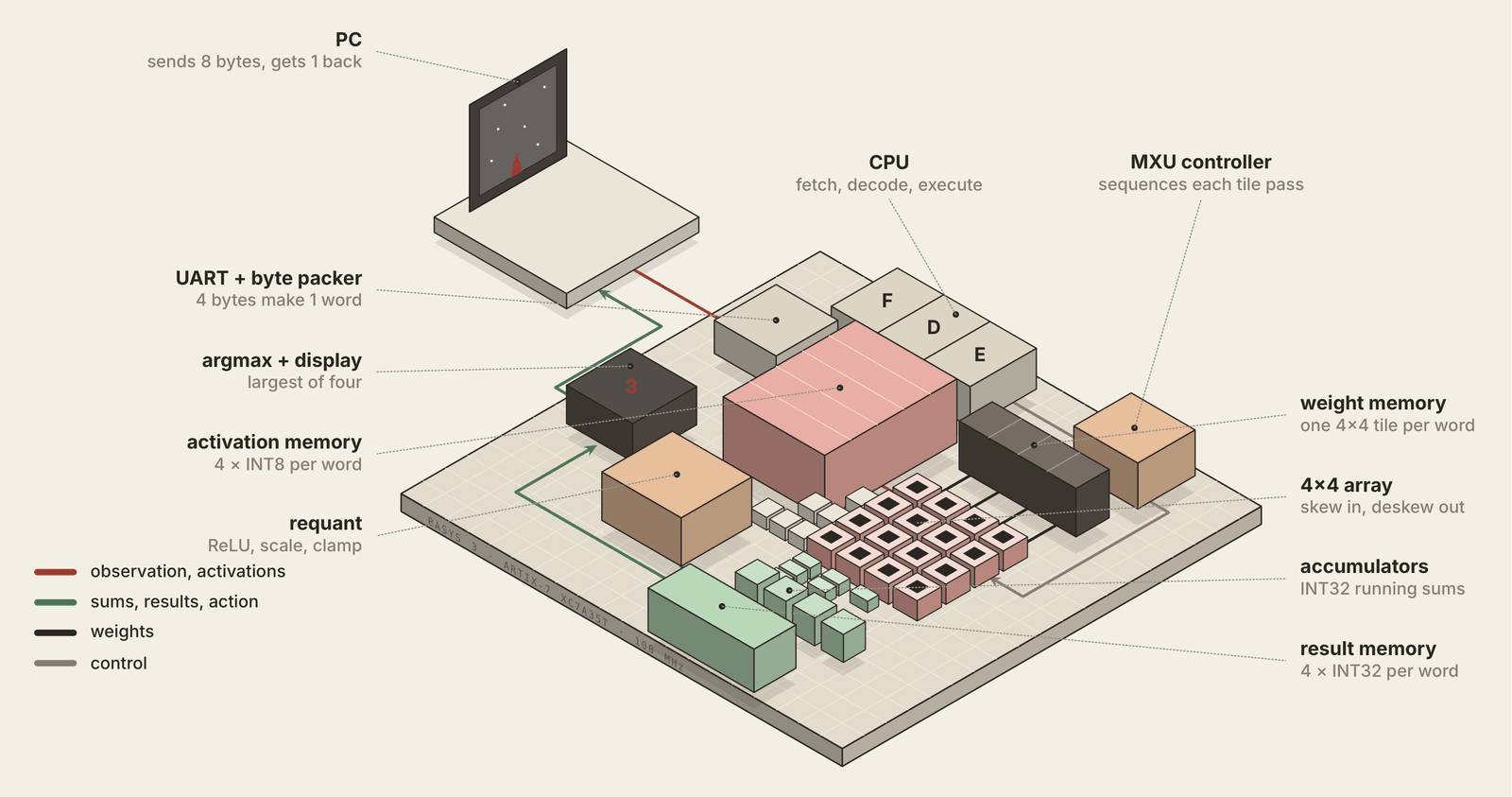
Around the array and the CPU sit three memories, a requant block, an argmax and a UART. Here is all of it.
Memories as wide as the array
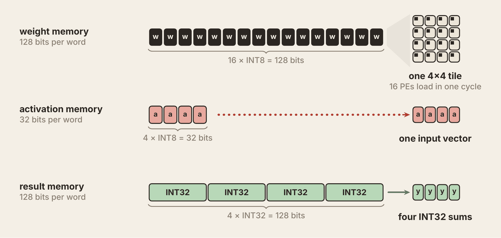
Weight memory is 128 bits wide, exactly one 4x4 tile of INT8 weights, so M_LD_W fills all 16 PEs in one read. Activation memory is 32 bits, one 4-element input vector. Result memory is 128 bits, four INT32 sums. A memory that handed over one number per cycle would starve the array.
Requant and argmax
When a group of outputs is done, requant turns each INT32 sum into INT8 for the next layer. Negative sums become 0, which is the ReLU. The rest are multiplied by 885,580 and shifted right by 24 bits, about × 0.053, then capped at 127. ACT triggers this and writes the results back into activation memory. Where that constant comes from is covered in the quantization section.
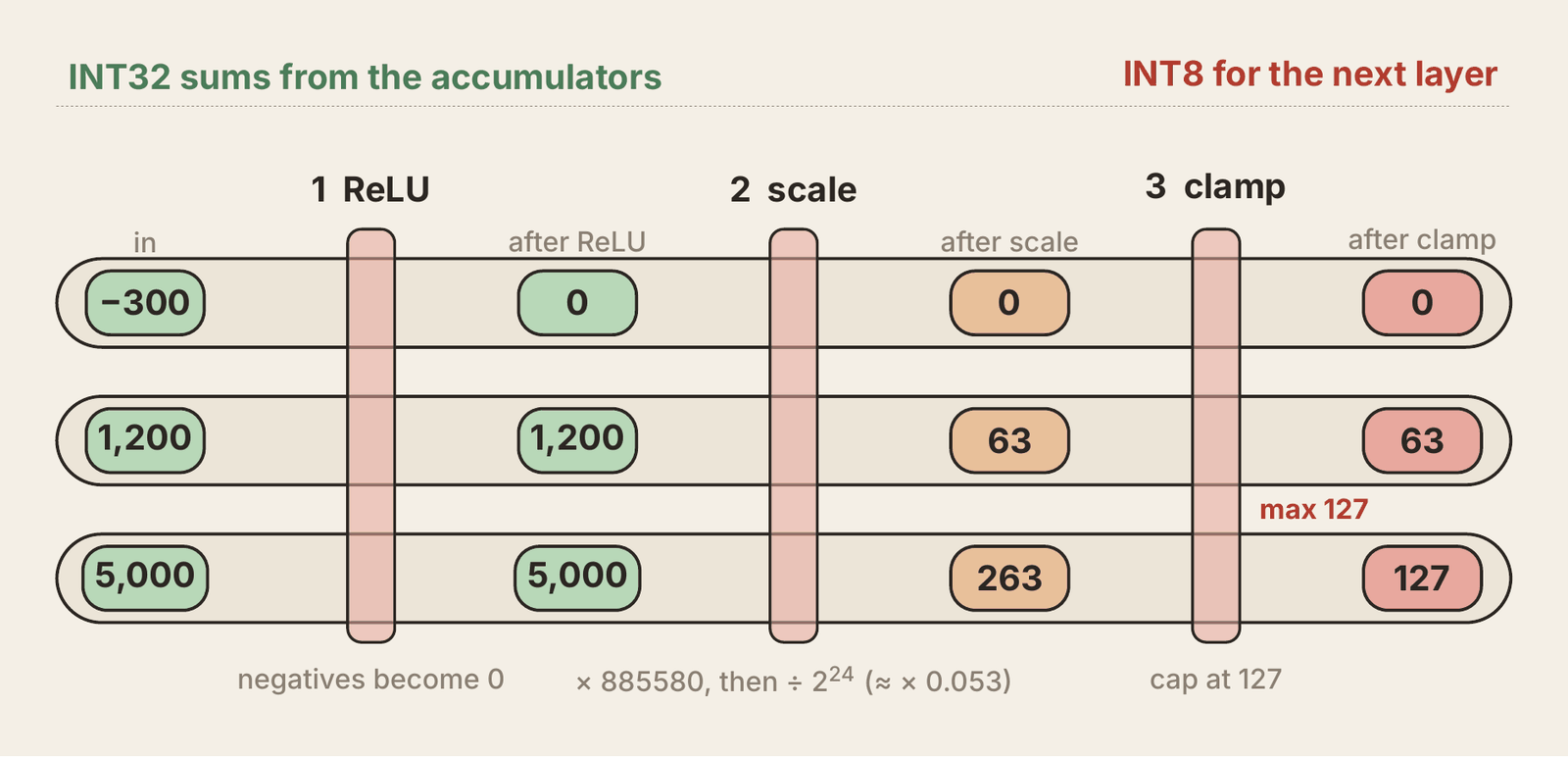
The last layer skips requant. Its 4 sums go to an argmax that compares outputs 0 and 1 and outputs 2 and 3 in parallel, then compares the two winners. Only the order matters, so the sums never get converted back to real numbers. The result is a 2-bit action.
UART in, action out
The PC sends 8 bytes at 115,200 baud. A byte packer groups them into two 32-bit words in activation memory. The CPU sits in reset until the 8th byte lands, then runs the program from address 0. The action goes back as one byte and shows on the seven-segment display.
The wire is slower than the network
- Layer 1: 32 groups × 3 tile passes
- Layer 2: 32 groups × 33 passes
- Layer 3: 1 group × 33 passes
That is 1,185 passes at about 20 cycles each, 24,290 cycles in total, or 0.24 ms at 100 MHz. The 9 bytes over UART take 0.78 ms, more than 3 times as long as the whole network.
The workload: a LunarLander policy
I picked a control task over a classifier on purpose. A classifier answers once. A policy runs in a closed loop where each action changes the next observation, so errors compound and a wrong answer shows up as a crash.
Every frame, LunarLander gives the agent 8 numbers (position, velocity, tilt, spin and two leg contacts) and asks for one of 4 actions: do nothing, or fire the left, main or right engine.
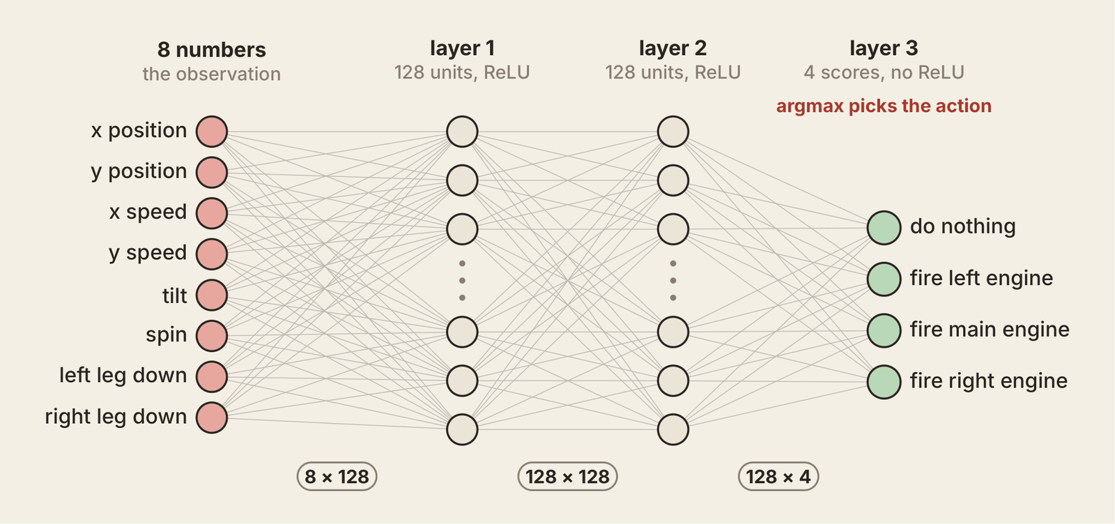
The policy is 8 → 128 → 128 → 4 with ReLU on the hidden layers, about 18,000 weights. I trained it with PPO for 300,000 steps on a CPU. The game counts 200 points as solved.
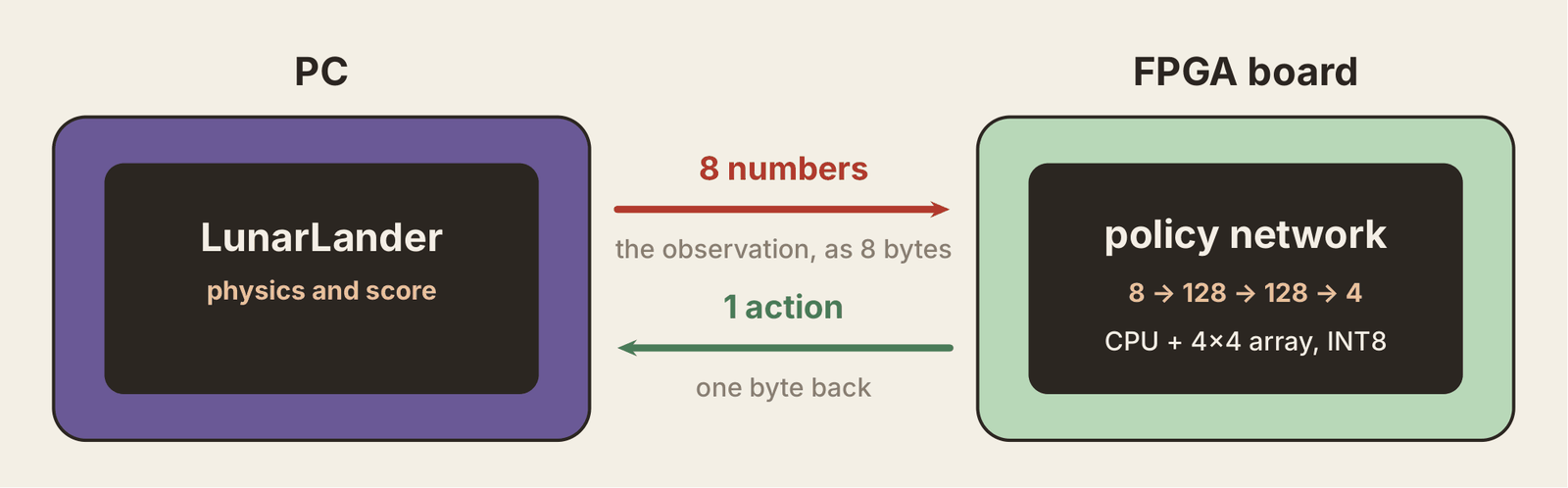
The catch is that PPO trained it in floating point and the board only does INT8.
Quantization
The board only does INT8, so the float network has to be converted. Most of that is standard. The interesting part is a constraint the hardware forced on me: one rescale constant for the whole network.
INT8 is what keeps the hardware small. One INT8 multiply fits in one DSP slice, and a 128-bit read carries 16 INT8 weights instead of 4 floats.
One scale per tensor
An INT8 is a whole number from -128 to 127. To convert a tensor, pick a scale s so its largest value lands on 127, then store round(x / s). Multiplying by s gets the real value back.
The inputs never go past 10, so their scale is 10 / 127, about 0.0787. A horizontal position of 0.5 becomes 6 and a leg touching the ground (1.0) becomes 13.
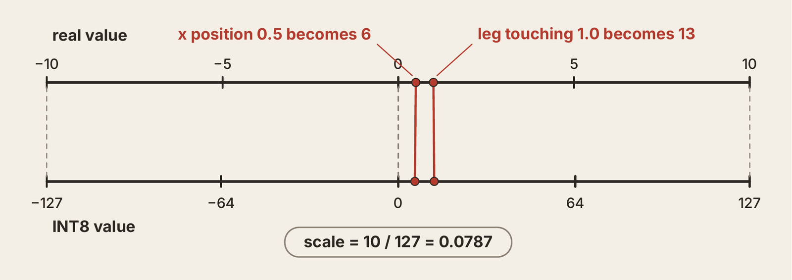
Each weight matrix gets its own scale from its largest weight. The whole conversion is three lines.
def quantize(w):
    scale = np.abs(w).max() / 127
    return np.clip(np.round(w / scale), -128, 127).astype(np.int8), scale
Back to INT8 after every layer
An INT8 × INT8 sum lands in INT32, in units of input scale × weight scale. The next layer wants INT8 at the activation scale, so every sum gets multiplied by input scale × weight scale / activation scale, about 0.0528 here. The activation scale comes from calibration: I run 700 recorded game steps through layer 1 and map the largest output to 127.
Hardware cannot multiply by 0.0528, so it multiplies by a whole number M and shifts right by S bits, which costs only wiring. I fixed S = 24 and set M = round(0.0528 × 2^24) = 885,580. A sum of 1,200 becomes 1,200 × 885,580 = 1,062,696,000, and shifting that right by 24 gives 63.
The trade: one constant for every layer
There is one requant block with one M and one S, so both layer boundaries have to share a ratio. Normally they would not, since each matrix picks its own scale. So I worked backwards. Both hidden layers share one activation scale, and layer 2's weight scale is set equal to layer 1's ratio, which makes layer 2's ratio identical.
The cost is that layer 2's weights only span -11 to 11 instead of -127 to 127, about 4.5 bits of precision instead of 8. The network is small enough that it still lands the lander. I spent precision to save hardware.
Folding the bias
A layer is y = Wx + b. The array only multiplies and adds, so the bias goes in as one extra row of weights, and the input gets one extra element, a constant 127 the board writes at startup. The multiply then adds the bias for free. The cost is a 129th input, which is why each group of 4 outputs takes 33 passes and not 32.
From numbers to memory files
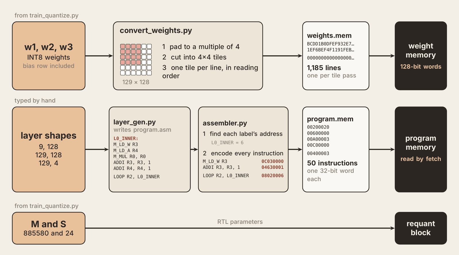
convert_weights.py pads each matrix to a multiple of 4, splits it into 4x4 tiles and writes one 128-bit tile per line, in the order the program reads them. That way the program only adds 1 to an address after each pass. The file has 1,185 lines, one per pass. layer_gen.py writes the assembly from the layer shapes, and a two-pass assembler resolves the labels and emits the 50 instructions in program.mem. Both files are loaded into the memories at startup.
Verification: does the hardware match the model?
The hardware matches a NumPy integer model bit for bit, at every layer, on every test input. Here is how that was checked, and what it does not prove.
Bit-exact at five checkpoints
I wrote a NumPy model that does the same integer math in the same order: INT8 multiplies, INT32 sums, ReLU, the multiply-and-shift requant and the clamp to 127. Then I ran the full design in simulation with cocotb and Verilator, which lets a Python test drive the clock and read every signal.
The test feeds 20 recorded observations through the hardware, one at a time. For each one it compares the hardware with the model at five points: the layer 1 sums, the layer 1 outputs after requant, the layer 2 sums, the layer 2 outputs and the 4 final scores. Last, it checks that the action on the display is the argmax of those scores. All 20 match exactly at every point.
Exact equality is the useful bar. A skew that is one cycle off or a requant shift that is one bit off would change some number and fail the test.
What it does not prove
The hardware can be exact and still play badly if quantization damaged the network. The only fair test of that is to let it play the game, which the results section covers.
Onto silicon
Simulation shows the logic is right. Synthesis shows whether it fits on a real chip and runs at speed.
Most of the chip is still empty
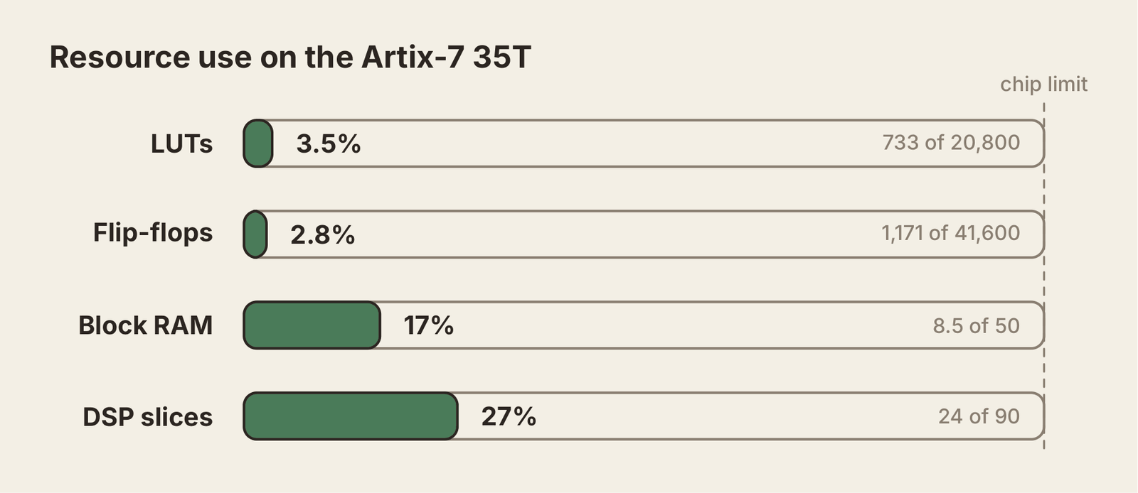
Vivado maps the design onto the Basys 3's Xilinx Artix-7 35T. The two numbers that matter are DSP slices and block RAM. 16 of the 24 DSPs are the PEs. The other 8 sit in the requant block, which has four 32-bit multipliers. Block RAM holds the weights, the program and the activations, and it sits at 17%. A whole CPU plus a matrix engine for a real network leaves room for a bigger array or a second one.
Timing
I asked for 100 MHz, which is 10 ns per cycle. The worst path finishes with 0.253 ns to spare. The slack is positive, so the design is safe at 100 MHz, though not by much.
On the board
The board's USB port doubles as the UART bridge, a button is the reset and the rightmost seven-segment digit shows the last action, 0 to 3. On the PC, a Python script runs the game, sends the 8 quantized observations each frame at 115,200 baud and steps the game with the byte that comes back. The laptop is only the eyes and hands. The policy runs entirely on the chip.
Results and what's next
The real test of a policy is whether the lander lands. Over 20 episodes the trained policy scores a mean reward of 261.2. LunarLander counts as solved at 200, so the policy is a good one.
The chain is complete: a network trained in PyTorch, squeezed to INT8, turned into weight and program files and run by a custom CPU and a 4x4 matrix engine on a Basys 3.
What I would do next
The chip is mostly empty, so the obvious next step is to use it. An 8x8 or 16x16 array would cut the number of passes per layer and bring the compute time down. The toolchain already turns layer shapes into programs, so a bigger network only means regenerating the memory files.
The other direction is throughput. Right now the array runs one input vector per tile, which throws away the weight reuse a systolic array is built for. Streaming a batch through each loaded tile would push the design closer to what the dataflow can do. And since the UART is already the bottleneck, a faster link would matter before any of that shows up end to end.